Smart Systems
Product Direction

From two boxes to one compact node inside the fitting.

Our next-generation emergency lighting node is smaller, mains-powered and wired directly to the battery connector of the fitting. It monitors the battery, runs the statutory tests automatically, and now confirms with its own light sensor that the LED actually lit.

70 × 40 × 13mm node
No batterymains powered
NB-IoTno gateway needed
Light sensorverified output
Where we are

The current node is proven in the field

The first batch is deployed and performing well. It does the job, but it was designed as two separate parts and it carries its own battery, which limits where it can go and how small it can be.

Current node

Two parts, own battery

  • A breaker box inside the fitting, plus a separate node mounted alongside it
  • Five-wire harness between the two parts
  • Battery inside the node, with its own service life to manage
  • Enclosure size dictated by that battery
  • Test results inferred from battery current alone
Next generation

One node, one P-Box, no battery

  • Node small enough to sit inside the fitting, as a boxed unit or bare PCBA
  • P-Box carries the mains conversion and the test relay
  • Powered entirely from the fitting's mains supply
  • Wired inline with the existing battery connector
  • Light sensor confirms the LED actually illuminated
What changes

Five changes, one goal: disappear into the fitting

Every change below exists to make the node easier to fit, cheaper to install and more certain in what it reports.

1

Smaller in every dimension

The enclosure comes down to 70 × 40 × 13 mm, small enough to tuck behind the light PCB in most fittings rather than sit beside them.

2

Fit the bare board

Where space is tight, the 65 × 33 × 8 mm PCBA can be installed without its plastic housing, directly inside the light.

3

The battery comes out

The node draws its power from the fitting's own mains supply, converted to DC in the P-Box. One less consumable, one less failure point, one less thing to replace on site.

4

A light sensor is added

A small sensor on a 30 cm lead watches the LED itself, so a passed test means light was actually produced, not merely that current flowed.

5

Portal and app move on

The online portal and mobile app gain new capability alongside the hardware, so the richer data coming off the node is actually usable on site.

What stays the same

The node still reports over NB-IoT with no gateway, no local network and no building infrastructure. Installation stays a wiring job, not an IT project.

Architecture

How the parts sit together

Three components go into the fitting: the node, the P-Box and the light sensor. The node is the intelligence, the P-Box handles mains and switching, the sensor closes the loop on the test.

EMERGENCY LIGHT FITTING AC Mains In existing supply Battery existing pack Light PCB LED + driver P-Box AC/DC conversion Test relay Battery current sense 61.5 × 51 × 25 mm Light Sensor 55 × 16 × 8 mm, 30 cm lead Node 70 × 40 × 13 mm NB-IoT · measurement · control mounts inside or on the fitting boxed or bare PCBA mains battery connector switched mains sees LED 7-wire harness power · battery · relay 4-wire I²C, 30 cm

Node

Cellular radio, processor, measurement and control. It decides when to test, records what happened and reports it. Fits inside the fitting or, where there is no room, on top of it.

P-Box

Converts the fitting's mains supply to the 5 V the node runs on, carries the relay that simulates a mains failure, and passes the battery through for measurement.

Light sensor

Tapes down facing the LED on a 30 cm lead and reports over I²C. Placement is flexible: behind the PCB, beside it, or outside the housing on a sealed fitting.

Installation

It wires into the battery connector

This is the heart of the design. Every emergency fitting already has a battery on a connector. The node goes inline with it, so the existing wiring is the installation point.

Battery existing pack P-Box current sense relay Node measures Battery + Battery − 5 V sense The pack stays in circuit. Nothing about the fitting's own emergency function is altered.

The eight signals on the harness

1GNDreference
25.0 V DCnode supply
3Breaker Control 1relay
4Breaker Control 2relay
5Battery Inmeasurement
6Battery Outmeasurement
7GNDreference
8NCspare

The light sensor runs on its own four-wire lead: I²C clock, I²C data, sensor supply and ground, terminated in a four-pin connector that plugs straight into the node.

1

Test on schedule

The relay drops the mains feed to the fitting, exactly as a real power failure would.

2

Measure the battery

Current and voltage are read through the inline connection while the fitting runs on battery.

3

Confirm the light

The sensor reports whether the LED actually illuminated and stayed lit for the duration.

4

Report it

The result goes out over NB-IoT to the portal, ready for the compliance record.

Form factor

Three small parts

Sizes are what make this fit where the current design cannot. The node body has been shortened to 70 mm, and the bare board is smaller again.
status LEDs · button 70 mm 40 mm 13 mm
Node — 70 × 40 × 13 mmBoxed unit with status LEDs and a single button. The bare PCBA measures 65 × 33 × 8 mm and can be fitted without the housing where space is tight.
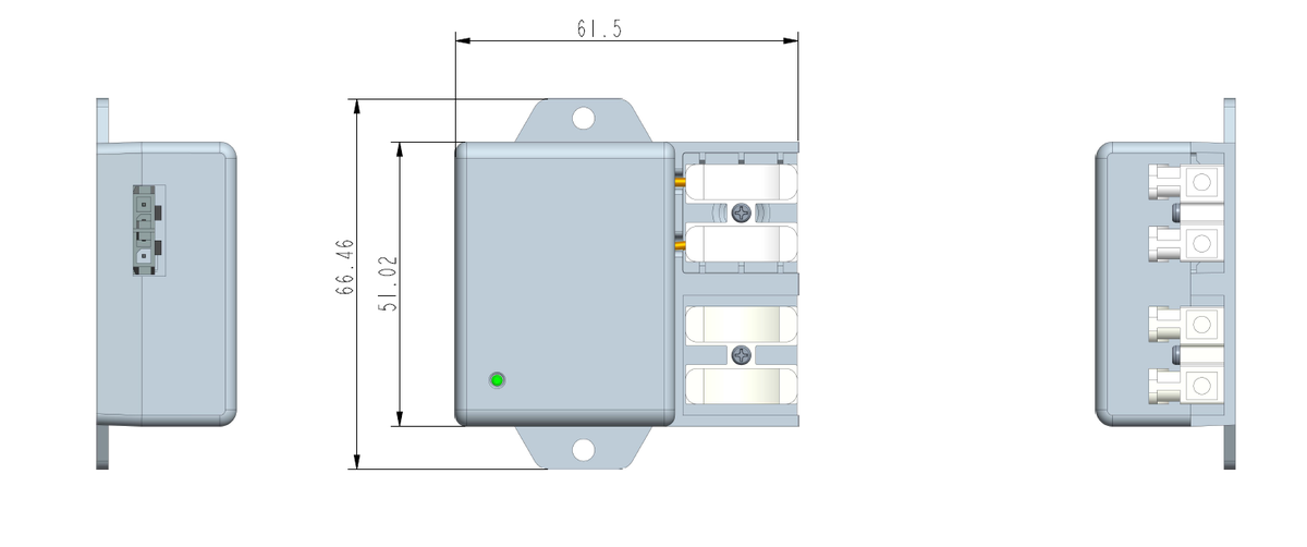
P-Box mechanical drawing with mounting tabs and terminal block
P-Box — 61.5 × 51 × 25 mmMounting tabs top and bottom, terminal connections on one face. Houses the AC/DC conversion and the test relay.
Light sensor mechanical drawing with four-pin connector
Light sensor — 55 × 16 × 8 mmFour-pin connector plugs into the node. The 30 cm lead is long enough to reach any practical mounting point in the fitting.
PartDimensionsNotes
Node, boxed70 × 40 × 13Status LEDs, button, antenna
Node, bare PCBA65 × 33 × 8For installation inside the light
P-Box61.5 × 51 × 25AC/DC and relay
Light sensor55 × 16 × 830 cm lead, I²C

Inside the node

  • Processor with NB-IoT module, SIM and cellular antenna
  • Current and voltage measurement across the battery connection
  • Relay driver for the mains test
  • Power circuit fed from the P-Box
  • Status LEDs and a single on/off button
  • Accelerometer available as an option
Compatibility

It fits the fittings already on the wall

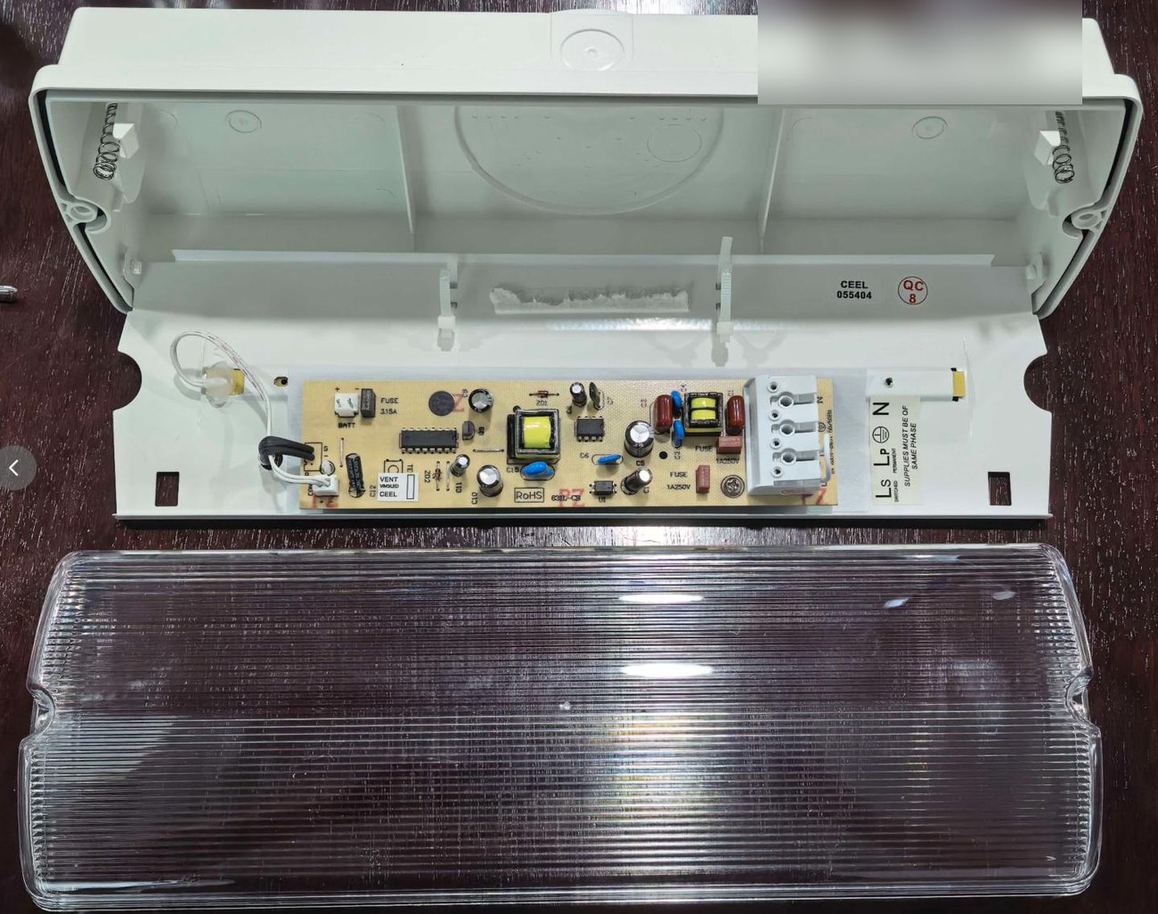
We assessed the design against a range of real fittings. In every case there was a workable home for the node, the P-Box and the sensor. What changes between fittings is where each part sits, not whether it can be done.
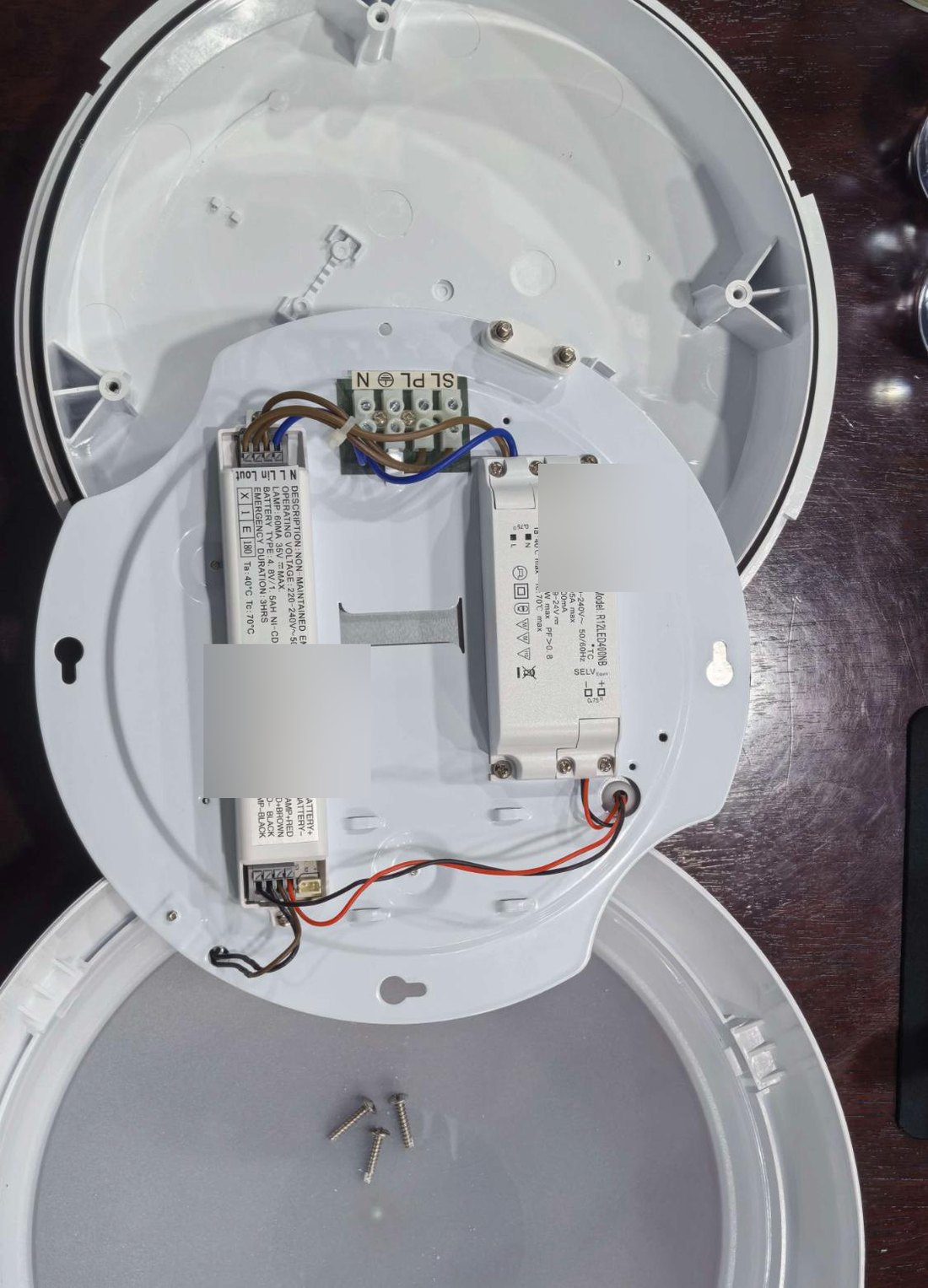
Round bulkhead fitting opened, showing the gear tray
Round bulkheadSpace behind the light PCB takes both the node and the P-Box. The sensor tapes to the reverse of the board where it still sees the LED.
Fitting with gear tray, showing space for the node
Gear tray fittingThe sensor mounts on the same side as the LED, taped down, with node and P-Box behind the board.
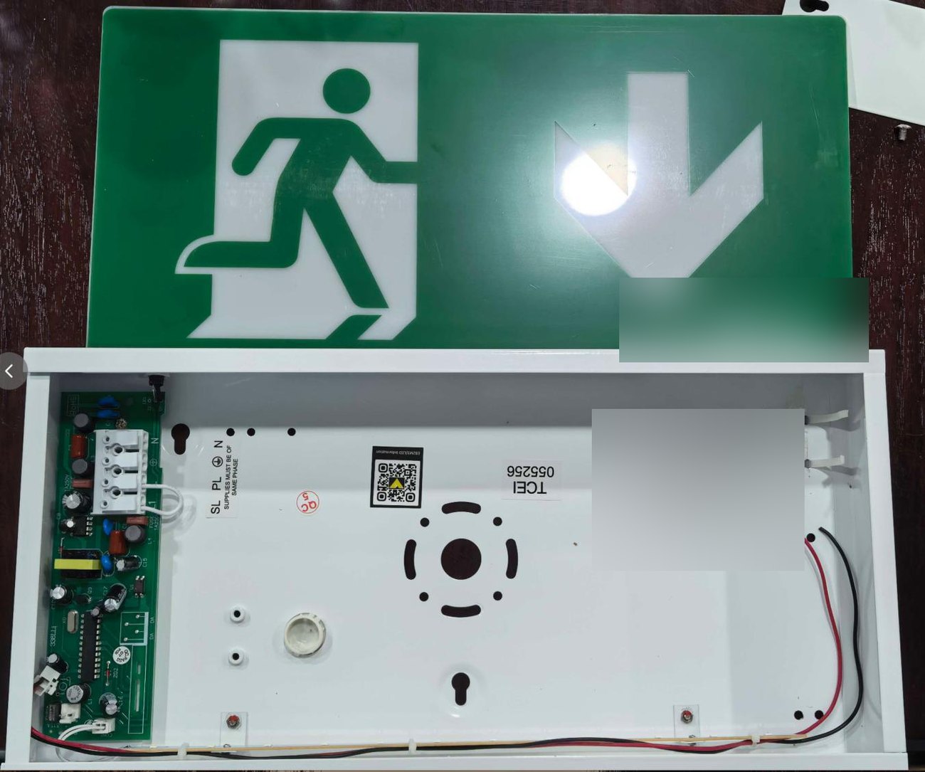
Exit sign box opened showing internal tray
Exit sign, openedThe enclosure that carries the light PCB has room alongside it for both units, with the sensor taped beside them.
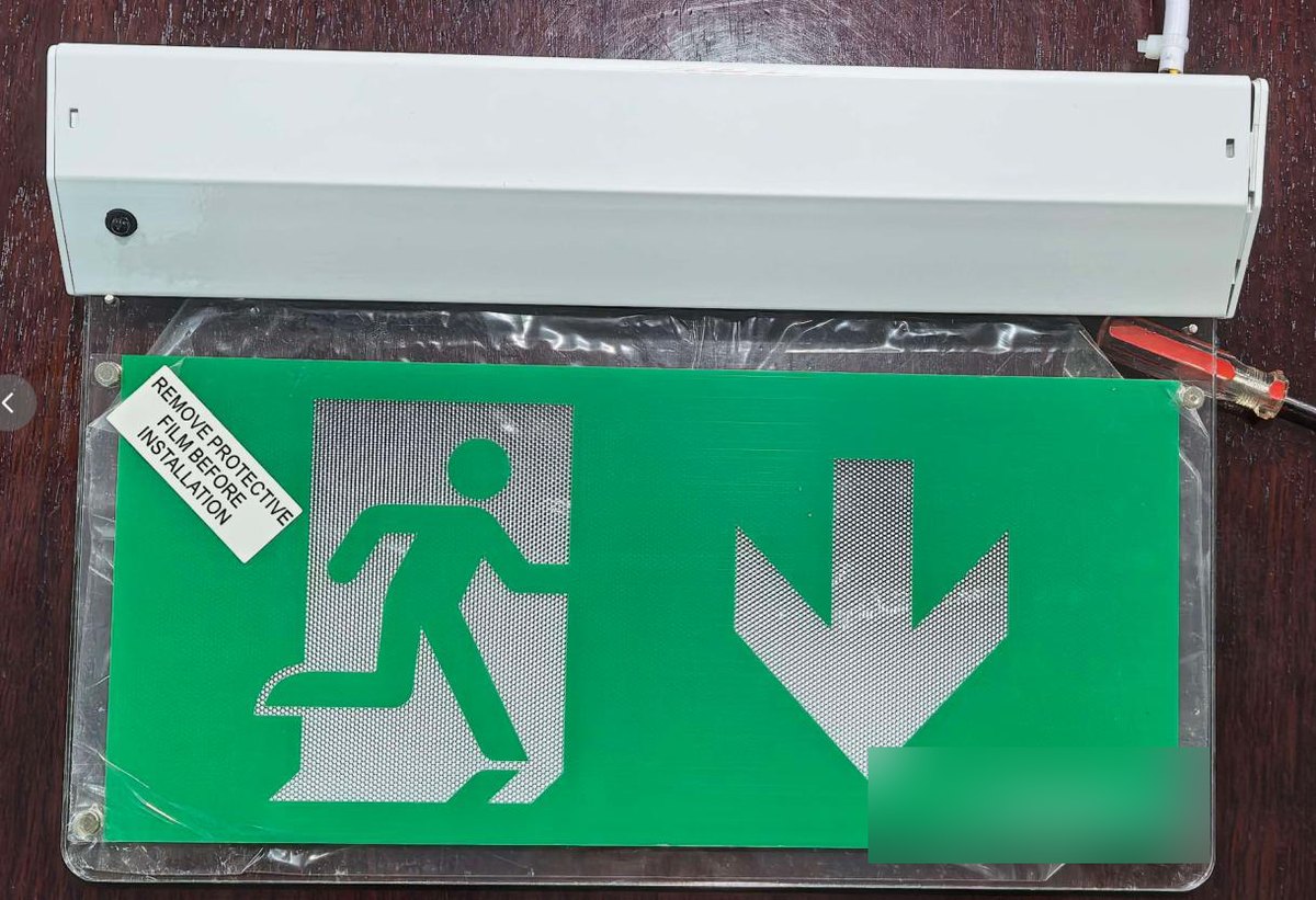
Surface bulkhead with exit panel
Sealed and edge-lit typesWhere the housing is closed, the node and P-Box mount externally, typically on top of the body, and the sensor sits where it can see the panel.
The one rule that matters. The light sensor must have line of sight to the LED. Everything else about placement is flexible; this single constraint decides where the sensor goes in each fitting type.
Software

The portal keeps the compliance record

Every test the node runs lands in the portal against the individual fitting, with the battery behaviour and the light sensor result recorded alongside it. The mobile app carries the same picture to whoever is on site.
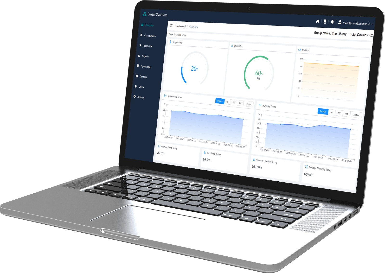
Smart Systems portal dashboard shown on a laptop
  • Every fitting listed individually, grouped by floor, zone or building
  • Automatic monthly and annual tests, with results dated and retained
  • Battery condition trended over time so failures are predicted, not discovered
  • Light sensor result recorded against each test, not just battery current
  • Exception reporting: the failures come to you rather than waiting to be found

Portal and app capability is being extended alongside this hardware; the new sensor data is what makes the extra detail possible.

Roadmap

From kick-off to production

Timings are calendar days measured from project kick-off, so the schedule holds whenever the start date lands.

Kick-off
Design startsRequirements confirmed and the mechanical and electrical design begins.
+70 days
Working samplesFunctional units available for us to put into real fittings and test on site.
+110 days
Design finalisedField feedback folded in, hardware and mechanical design frozen.
+120 days
CE certification completeCompliance testing finished and documented.
+120 days
Ready for mass productionProduction preparation complete, ready to build to order.
Our part in it. We define the requirements, review the design as it develops, and carry out the field testing and product acceptance that decides when the design is right.