
Our next-generation emergency lighting node is smaller, mains-powered and wired directly to the battery connector of the fitting. It monitors the battery, runs the statutory tests automatically, and now confirms with its own light sensor that the LED actually lit.
The first batch is deployed and performing well. It does the job, but it was designed as two separate parts and it carries its own battery, which limits where it can go and how small it can be.
Every change below exists to make the node easier to fit, cheaper to install and more certain in what it reports.
The enclosure comes down to 70 × 40 × 13 mm, small enough to tuck behind the light PCB in most fittings rather than sit beside them.
Where space is tight, the 65 × 33 × 8 mm PCBA can be installed without its plastic housing, directly inside the light.
The node draws its power from the fitting's own mains supply, converted to DC in the P-Box. One less consumable, one less failure point, one less thing to replace on site.
A small sensor on a 30 cm lead watches the LED itself, so a passed test means light was actually produced, not merely that current flowed.
The online portal and mobile app gain new capability alongside the hardware, so the richer data coming off the node is actually usable on site.
The node still reports over NB-IoT with no gateway, no local network and no building infrastructure. Installation stays a wiring job, not an IT project.
Three components go into the fitting: the node, the P-Box and the light sensor. The node is the intelligence, the P-Box handles mains and switching, the sensor closes the loop on the test.
Cellular radio, processor, measurement and control. It decides when to test, records what happened and reports it. Fits inside the fitting or, where there is no room, on top of it.
Converts the fitting's mains supply to the 5 V the node runs on, carries the relay that simulates a mains failure, and passes the battery through for measurement.
Tapes down facing the LED on a 30 cm lead and reports over I²C. Placement is flexible: behind the PCB, beside it, or outside the housing on a sealed fitting.
This is the heart of the design. Every emergency fitting already has a battery on a connector. The node goes inline with it, so the existing wiring is the installation point.
The light sensor runs on its own four-wire lead: I²C clock, I²C data, sensor supply and ground, terminated in a four-pin connector that plugs straight into the node.
The relay drops the mains feed to the fitting, exactly as a real power failure would.
Current and voltage are read through the inline connection while the fitting runs on battery.
The sensor reports whether the LED actually illuminated and stayed lit for the duration.
The result goes out over NB-IoT to the portal, ready for the compliance record.
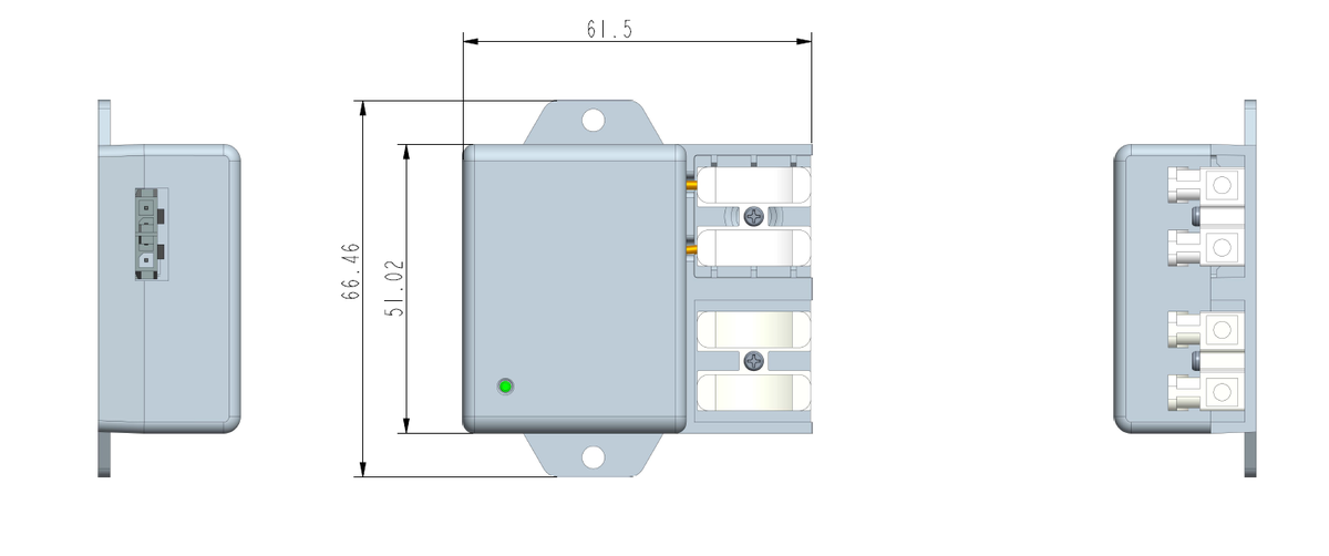
Sizes are what make this fit where the current design cannot. The node body has been shortened to 70 mm, and the bare board is smaller again.
| Part | Dimensions | Notes |
|---|---|---|
| Node, boxed | 70 × 40 × 13 | Status LEDs, button, antenna |
| Node, bare PCBA | 65 × 33 × 8 | For installation inside the light |
| P-Box | 61.5 × 51 × 25 | AC/DC and relay |
| Light sensor | 55 × 16 × 8 | 30 cm lead, I²C |
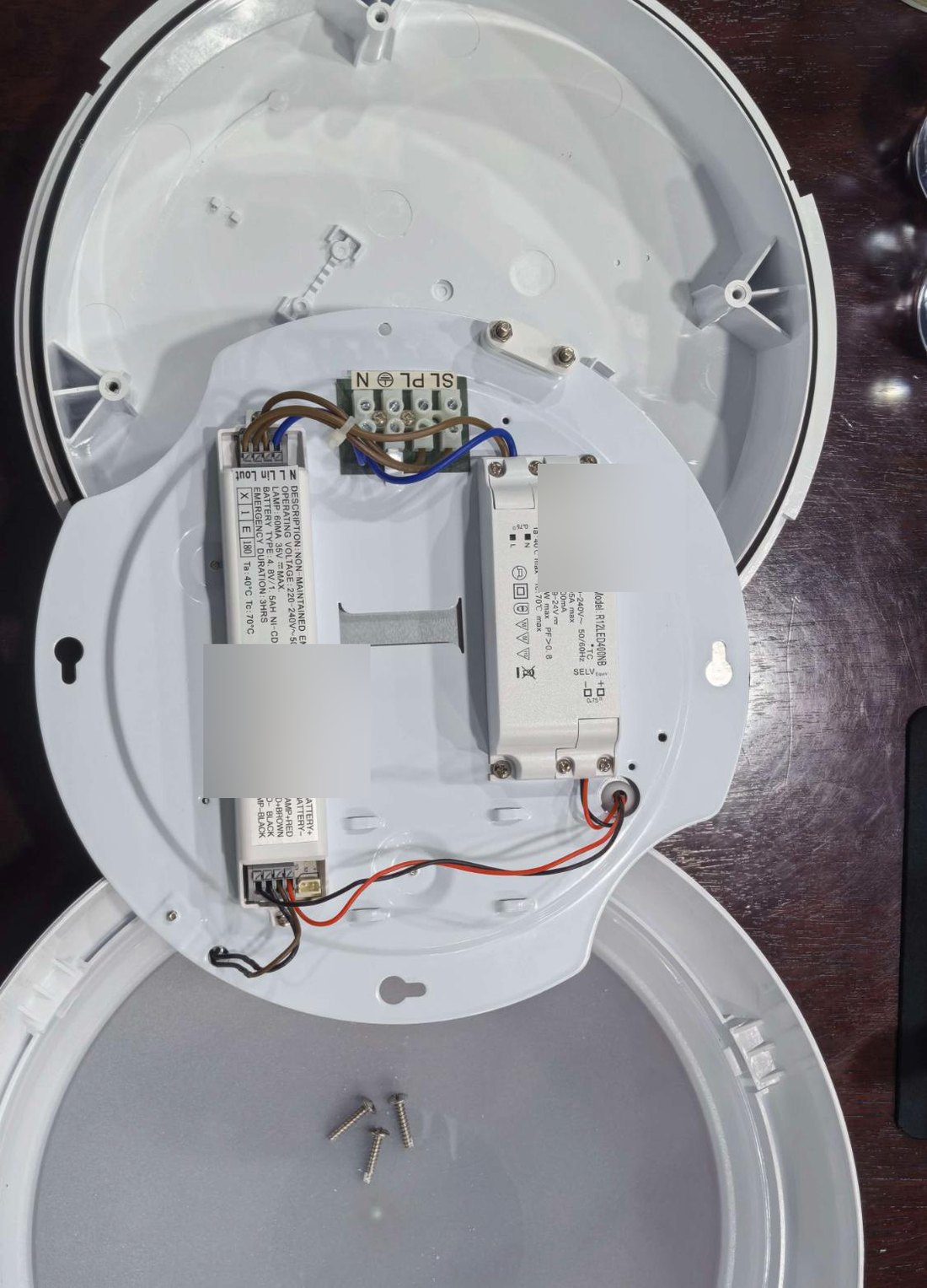
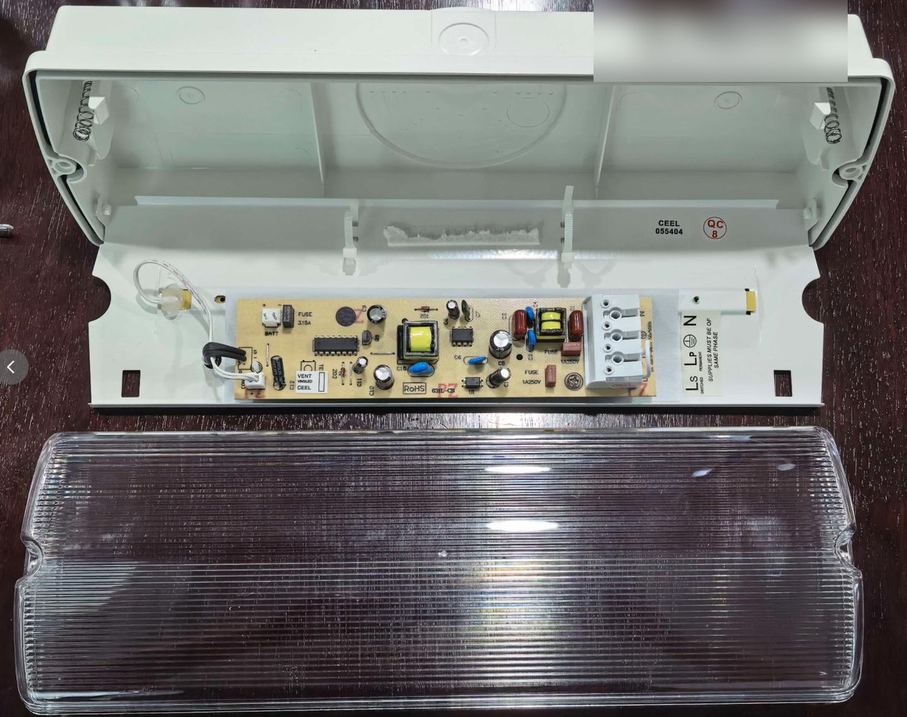
We assessed the design against a range of real fittings. In every case there was a workable home for the node, the P-Box and the sensor. What changes between fittings is where each part sits, not whether it can be done.
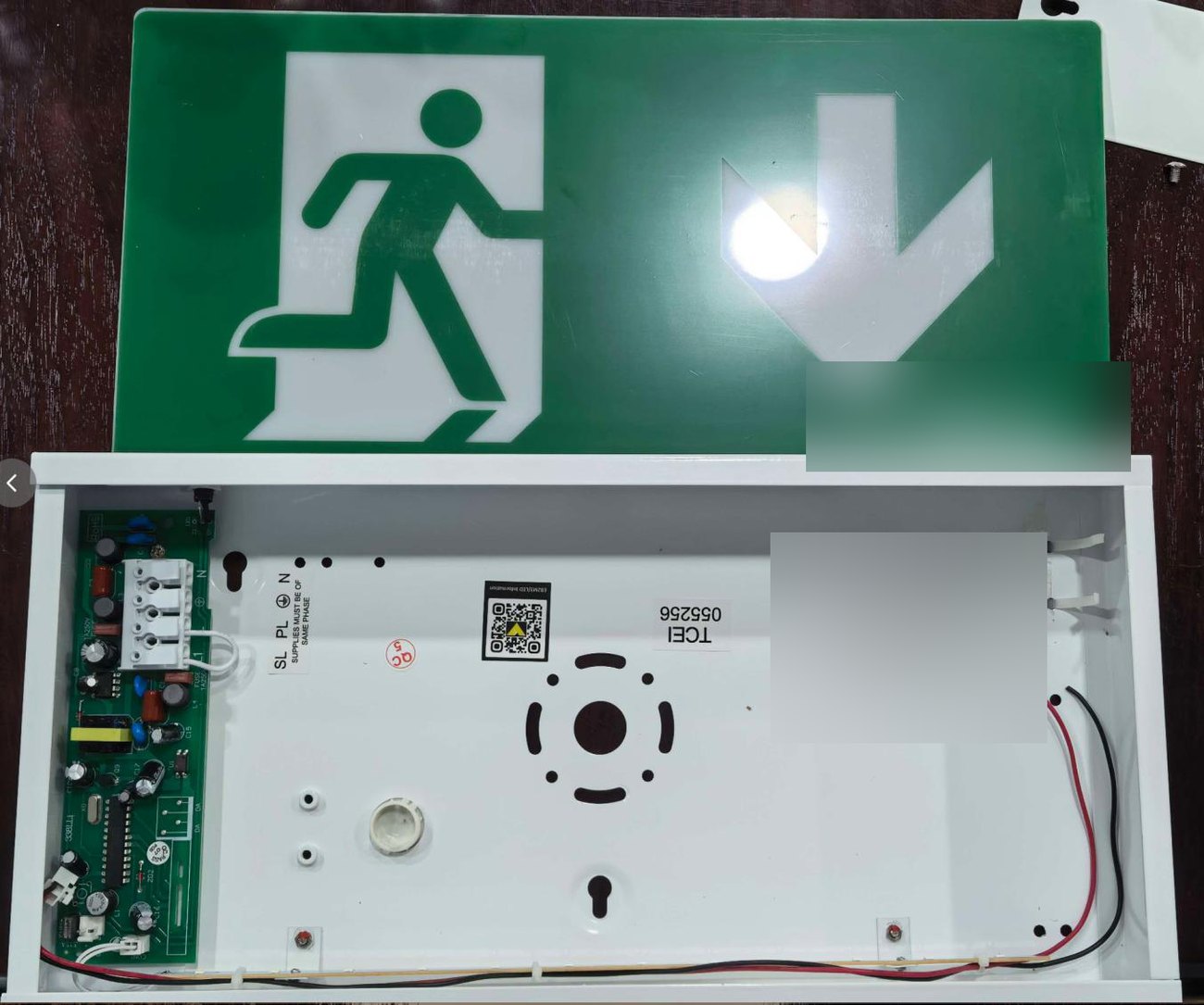
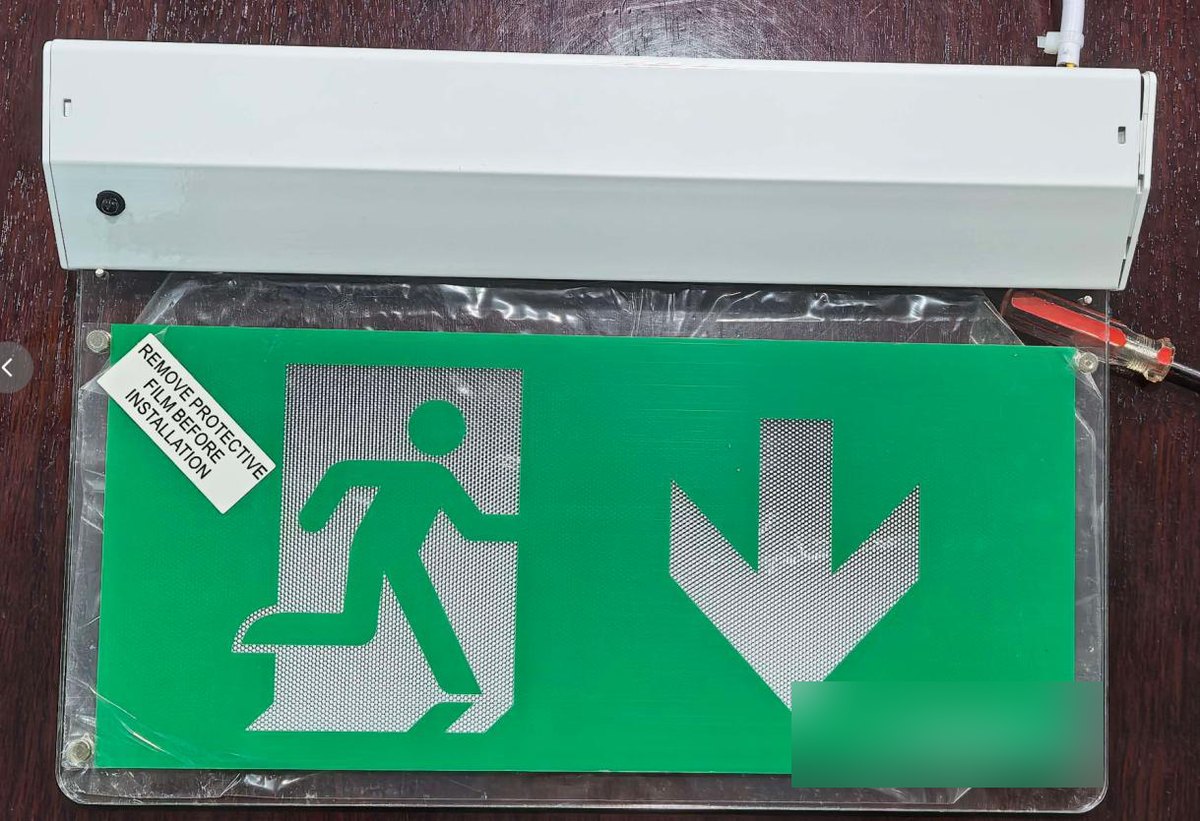
Every test the node runs lands in the portal against the individual fitting, with the battery behaviour and the light sensor result recorded alongside it. The mobile app carries the same picture to whoever is on site.

Portal and app capability is being extended alongside this hardware; the new sensor data is what makes the extra detail possible.
Timings are calendar days measured from project kick-off, so the schedule holds whenever the start date lands.